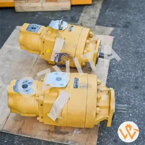
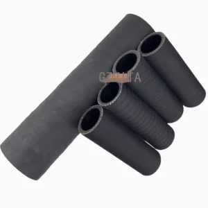
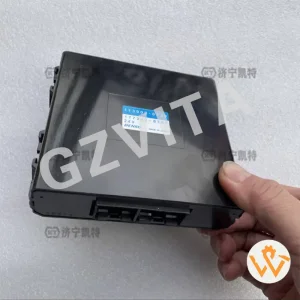
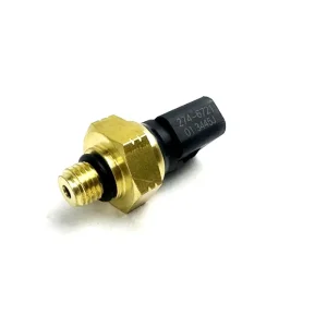
Discover our heavy-duty hydraulic parts, precise oil sensors, and custom electrical control units engineered for maximum field reliability.

In heavy-duty diesel engines and machinery, the fuel pump relay represents a mission-critical link between low-current command electronics and high-draw mechanical fuel delivery systems. Developing a comprehensive understanding of the fuel pump relay diagram is paramount for fleet operations, electrical system designers, and wholesale procurement managers alike. These diagrams illustrate the vital flow path from the ignition switch, pressure monitoring circuits, and the engine control module (ECM) down to the physical fuel feed pump mechanism.
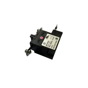
Historically, heavy equipment relied on mechanical linkage pumps. However, to meet strict global emission controls and efficiency guidelines, modern industrial engines employ high-pressure common rail fuel systems. These systems utilize electronic relay circuits to monitor fuel lines continuously. An accurate electrical diagram enables field service engineers to easily identify pin terminals—such as Terminal 85 (coil ground), Terminal 86 (coil trigger), Terminal 30 (constant high-current feed), and Terminal 87 (normally open load delivery to the pump). In 24V applications typical in excavators (including CAT, Komatsu, and Sany systems), high-amperage surges are mitigated by implementing built-in resistors or clamping diodes within the relay housing to absorb back-EMF, protecting sensitive control modules.
| Terminal Pin | Designation Standard | Functional Description (24V/12V Heavy duty) | Failure Diagnostic Indicator |
|---|---|---|---|
| Pin 30 | Constant Positive Feed | Direct fused line to the battery bus bar. Must maintain consistent high amperage. | Voltage drop indicates high resistance, corroded wires, or loose crimps. |
| Pin 85 | Relay Coil Ground | Return path path to chassis ground or ECM-switched ground. | Floating ground prevents relay engagement, causing crank-no-start. |
| Pin 86 | Relay Coil Control/Trigger | Receives command current from ignition key switch or safety ECU. | No voltage indicates faulty safety lock switch or key cylinder issues. |
| Pin 87 | Normally Open (N.O.) Contact | Switched high-current output path heading directly to the fuel pump motor. | No output during trigger indicates pitted or welded relay contacts internally. |
| Pin 87a | Normally Closed (N.C.) Contact | Optional output, often used for diagnostic indicators or secondary backup loops. | Not typically populated on single-stage heavy machinery fuel circuits. |
For procurement agents searching for global wholesale fuel pump relay factories, sourcing components that match precise schematic prints is vital. Off-spec relays with minor internal diagram differences can cause reverse polarity issues, blown main fuses, or controller area network (CAN-bus) errors. When selecting partners, industrial buyers must cross-reference wiring diagrams with engineering specifications to ensure compatibility across harsh operational conditions like vibration, moisture, and temperature fluctuations.
Sourcing relays with silver-alloy contacts ensures a long duty cycle under inductive loads, mitigating pitting and carbon build-up common in heavy equipment.
Factories must adhere strictly to ISO 9001:2015, CE, and RoHS certifications. Environmental sealing must meet IP67 or IP69K ratings for heavy excavations.
Working directly with factory-to-trade integrated companies reduces lead times, controls batch variances, and provides custom wiring schematic testing.
Procuring wholesale electrical control components introduces several challenges. A primary issue is the variance in terminal layout standards between North American, European, and Asian heavy machinery designs. For instance, DIN standard layouts differ significantly from Japanese Industrial Standards (JIS). Procurement teams must partner with companies that offer transparent diagnostic documentation, custom labeling, and detailed CAD-model mapping. This minimizes integration friction when replacing parts in complex machinery from major brands like Komatsu, Volvo, or Caterpillar.
Square Meters Workshop
Skilled Assembly Technicians
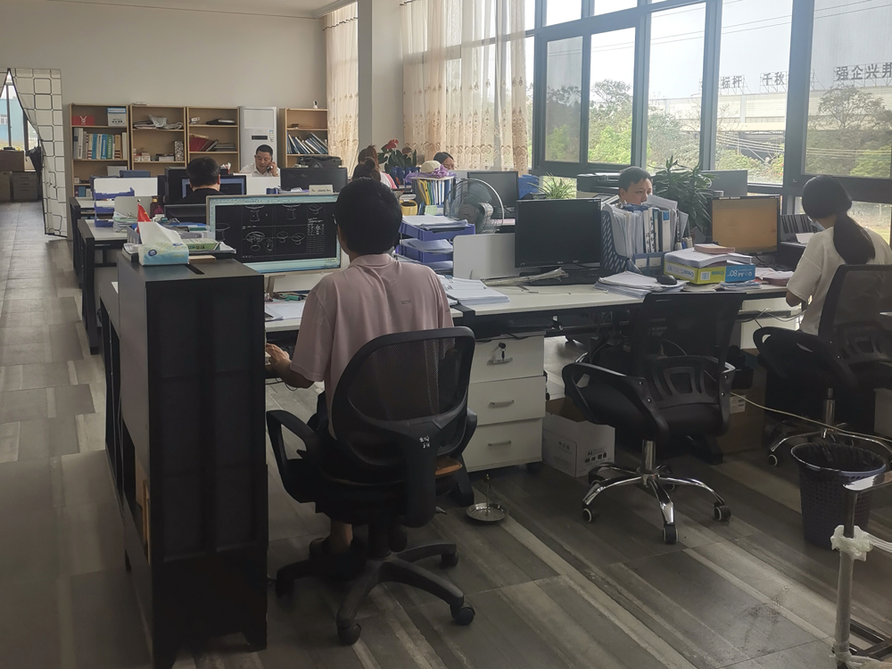
Expert Development Engineers
Global Machinery Brands Supported
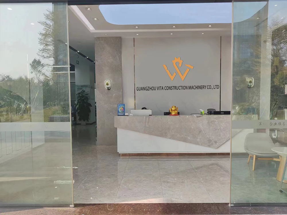
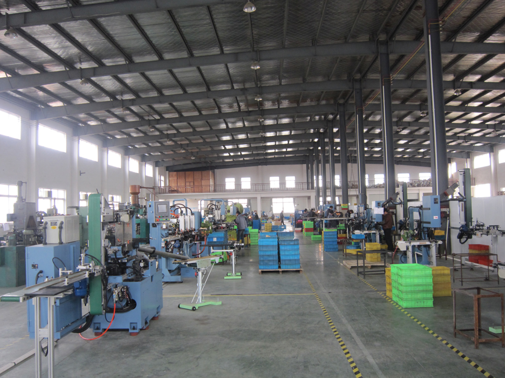
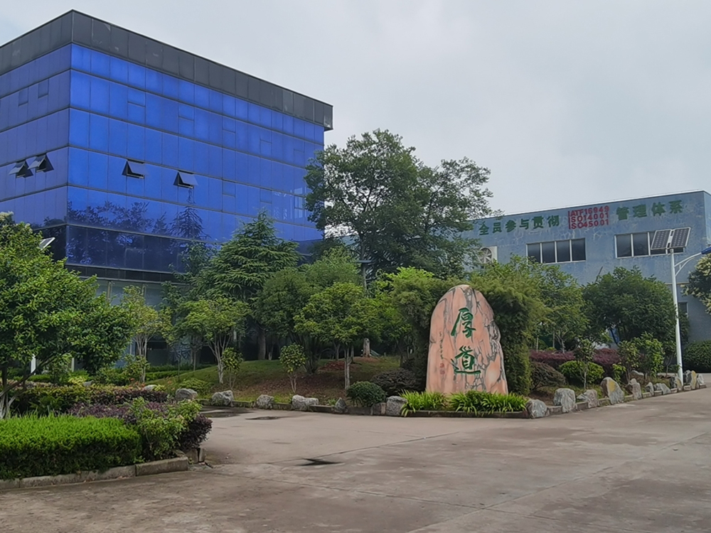
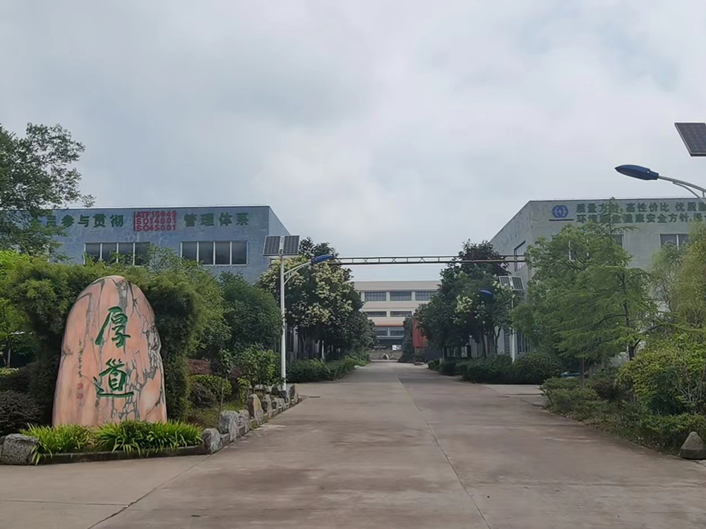
Guangzhou Vita Construction Machinery Co., Ltd. is one of the largest company that combines factory and foreign trade. The factory is located in Xiangyang City, Hubei Province, there are more than 18,000 square meters workshop with several advanced production machines, more than 278 well trained and skilled workers and around 8 experienced engineers assure the good product quality as well as fast and accurate delivery.
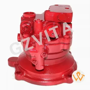
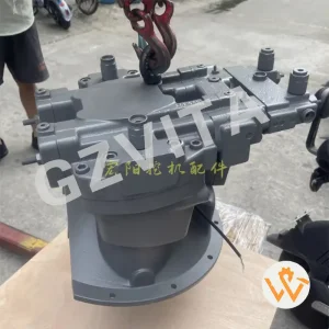
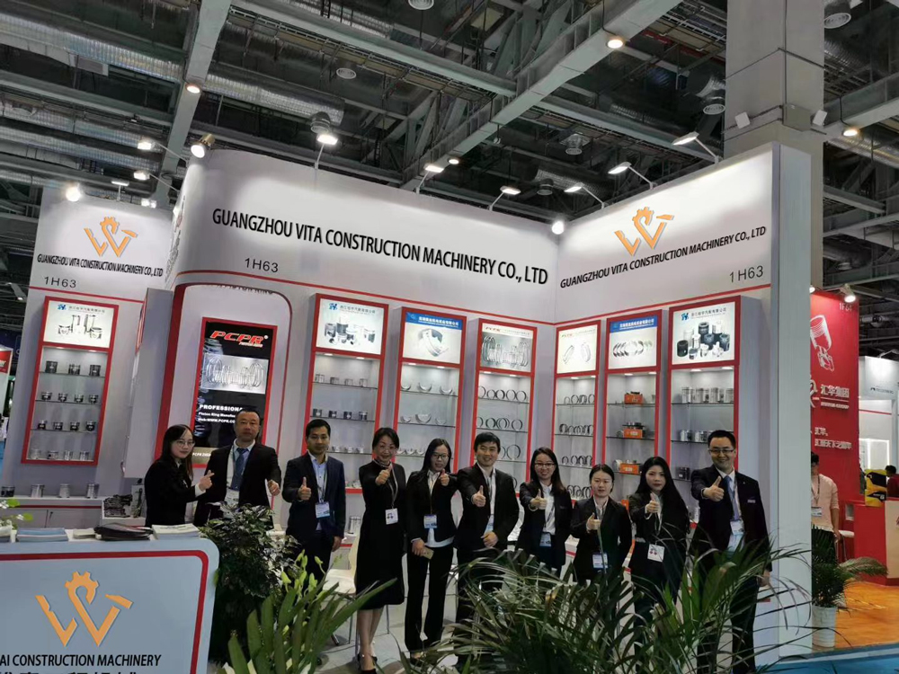
We specialize in producing, developing and selling the whole range of construction machinery parts. Such as engine assembly, hydraulic pump, final drive, electric generating set, engine bearing (Main bearings con Rod Bearing series), crankshafts, engine valves, gear pumps, cylinder, all kinds of filters, excavator bucket, undercarriage parts for excavator and bulldozer... which are used as replacement of many type of machines, the brand include Komatsu, Volvo, Sumitomo, Caterpillar, Kubota, Hitachi, John Deere, Kobelco, Hyundai, Kato, Sany, XCMG, SUNWARD, and other well-know brands.
In the fast-paced world of construction, the reliability and efficiency of your machinery can make or break a project. We understand that high-quality parts are essential for optimal performance. So we aims to provide top-notch construction machinery parts to make customer's machinery running smoothly.
To improve our service, we set up engine maintenance development. In addition to providing customers with engine assemblies, we can also help customers solve various technical problems encountered in the operation and assembly of engines.
We have our own professional maintenance team and can even be invited by customers to arrange for maintenance technicians to go abroad to help customers repair engines.
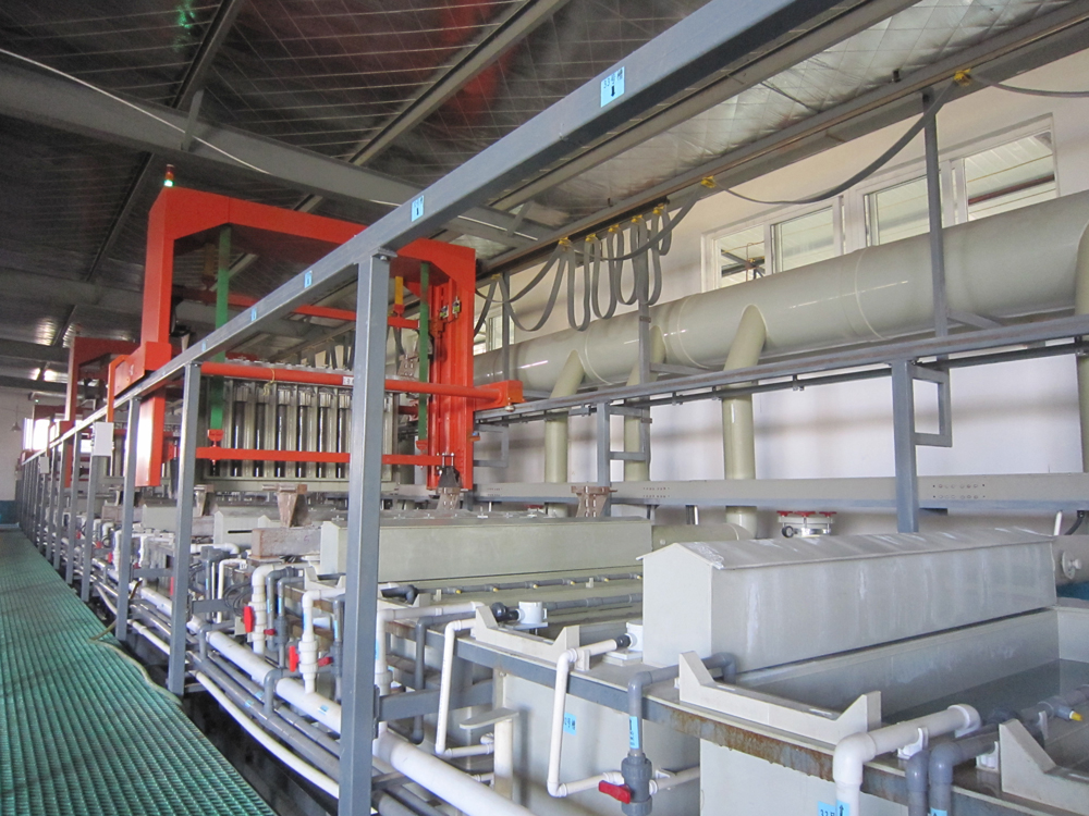
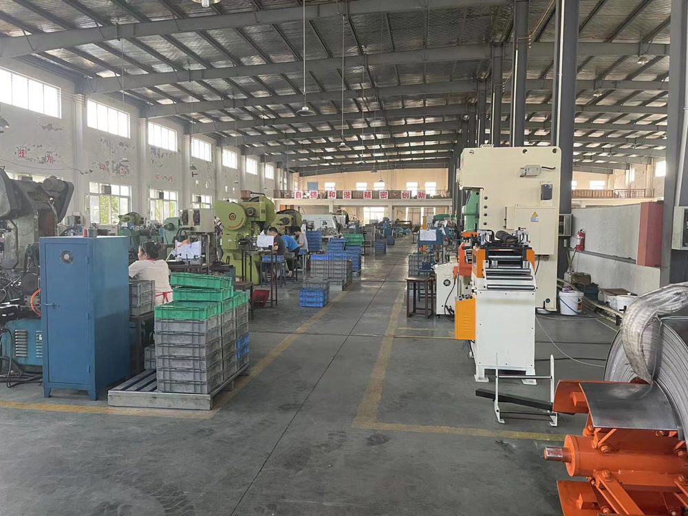
Our state-of-the-art facilities in Xiangyang, Hubei utilize advanced production machinery and rigorous quality control protocols.

Continuous optimization of heavy machinery electrical parts.
As the construction machinery industry trends towards electrification and hybrid drive systems, the standard mechanical fuel pump relay is undergoing a significant transition. The technical roadmap for the next decade centers on smart power distribution units (SPDUs), solid-state relays (SSRs), and IoT-enabled circuit breakers.
1. Solid-State Relay (SSR) Integration: Standard electromagnetic relays feature moving physical contacts that degrade over time due to electrical arcing. Solid-state relays utilize semiconductor switching elements (such as MOSFETs or IGBTs). This design offers near-infinite switching cycles, making them highly resistant to dust, shock, and extreme excavator operations.
2. CAN-Bus Connected Diagnostics: Modern fuel pump relays are evolving from passive components into active communication nodes. By integrating a local interconnect network (LIN) or CAN-bus transceiver directly into the relay micro-housing, the engine control module receives real-time telemetry. If a fuel pump draws excessive current (indicating a clogged filter or a failing motor), the smart relay flags the fault code before system failure occurs.
3. Dual-Voltage Compatibility (12V/24V/48V): The rise of hybrid construction equipment requires electrical systems to handle varying voltage architectures. Future relays must adapt dynamically, allowing for high-amperage fuel delivery switches while drawing minimal coil-trigger power from low-voltage circuits.
Get answers to critical technical questions regarding fuel pump relay diagrams, diagnostic procedures, and bulk ordering specifications.
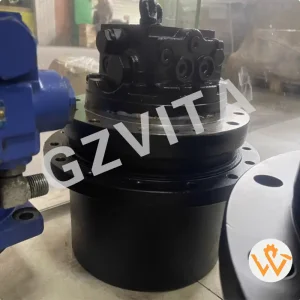
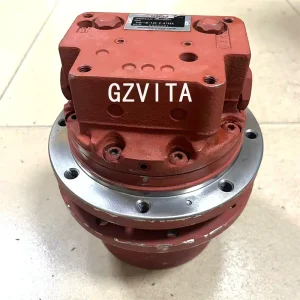
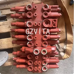
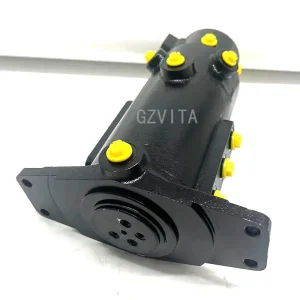
Explore our comprehensive range of high-durability final drives, main hydraulic pumps, and control panels built for harsh operational environments.