Wholesale PHV-390-53B Walking/Travel Device Komatsu Caterpillar Yuchai XCMG Takeuchi John Deere 35 40 Travel Motor Travel Reduction Gearbox Manufacturers, Suppliers

Hydraulic travel motors – Provide rotary power to the track wheels.

Dual independent motors – Allow for counter-rotation and pivot turns.

Travel control levers/pedals – Operator inputs for speed and direction.

Main hydraulic pump – Supplies high-pressure oil to the travel system.

Travel control valves – Direct flow from the pump to the left or right motor.

Two-speed travel selection – Switches between high-speed and high-torque modes.

Speed change valve – Alters motor displacement for speed shifting.

Travel reduction gearbox (final drive) – Reduces motor speed and increases torque.

Sprocket drive – Final drive output shaft directly turns the track sprocket.

Planetary gear sets – Inside the reduction gearbox for compact torque multiplication.

Swing bearings – Support the upper structure and allow it to rotate during travel turns.

Track frame – Rigid structure housing the final drive and rollers.

Hydraulic pressure release – Allows the machine to be towed by disengaging the motors.

Travel brakes – Typically spring-applied, hydraulic-release parking brakes.

Hydraulic counterbalance valves – Prevent uncontrolled movement on slopes.

Pilot pressure system – Provides low-pressure control signals to the main valves.

Neutral bypass – Routes pump flow back to tank when travel levers are not activated.

Load sensing system – Adjusts pump flow and pressure based on demand.

Track tension adjustment – Maintains proper tension via grease cylinders.

Track rollers and idlers – Support and guide the track chain.

Pivot turn (spot turn) – Achieved by driving one track forward and the other reverse.

Gradual turn – Accomplished by varying speed between the two tracks.

Straight-line travel – Both motors receive equal flow and pressure.

Auto-deceleration system – Redects engine speed when travel levers are neutral.

Travel alarm – Sounds when the machine is set to move.

Speed sensors (if equipped) – Monitor track speed for control or monitoring systems.

Travel pressure relief valves – Protect the system from overloads.

Case drain lines – Return internal leakage oil from motors back to the tank.

Hydrostatic transmission principle – Uses variable hydraulic flow for infinite speed control.

Integrated pump-motor circuit – Forms a closed-loop for efficient power transfer.

Product Description

The distribution valve assembly for JCB equipment is an essential component in the hydraulic system, responsible for directing hydraulic fluid to various functions of the machine, such as the boom, bucket, and other attachments. Here are the key components typically found in a JCB distribution valve assembly:
Key Components & Features

Valve Body

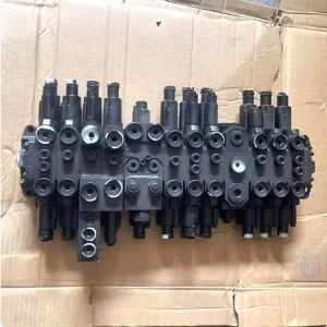
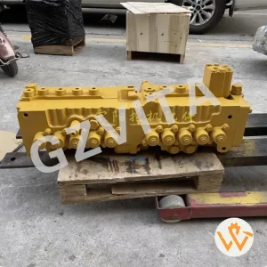
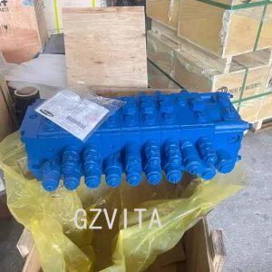
The main housing that contains the internal components and passages for hydraulic fluid.

Spool Valves

These are movable components within the valve body that control the flow of hydraulic fluid to different circuits. They can be shifted to direct fluid to specific functions.

Actuators

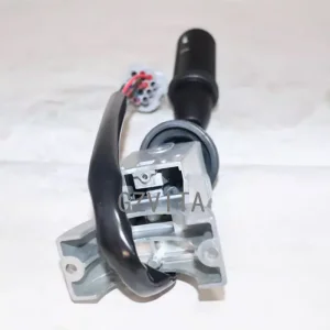
These components are used to operate the spool valves, often controlled by levers or joysticks in the operator's cab.

Seals and O-rings

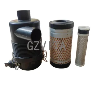
These are used to prevent hydraulic fluid leaks and maintain pressure within the system.

Ports and Connectors

These are the entry and exit points for hydraulic fluid, connecting the distribution valve to the hydraulic lines leading to various machine functions.

Pressure Relief Valve

This component helps protect the hydraulic system from excessive pressure by diverting fluid back to the reservoir when necessary.

Return Line

A pathway for hydraulic fluid to return to the reservoir after it has completed its work.

Mounting Bracket

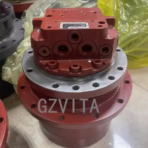
This secures the distribution valve assembly to the machine frame.

Frequently Asked Questions

What does the JCB distribution valve assembly do?

It serves as the control hub of the hydraulic system, directing high-pressure hydraulic fluid to various working parts of the machine, such as the boom, bucket, and attachments.

Why are seals and O-rings important in the assembly?

Seals and O-rings are critical for preventing hydraulic oil leaks and maintaining the necessary operating pressure within the system to ensure efficient machine performance.

How does a pressure relief valve protect the JCB hydraulic system?

It monitors the system pressure and automatically diverts excess fluid back to the reservoir if the pressure rises above safe limits, protecting hoses and components from damage.

How are spool valves controlled within the assembly?

Spool valves are shifted using actuators, which are linked to mechanical levers, joysticks, or electronic controls operated by the driver inside the cab.

What is the function of the return line in the distribution valve?

Once the hydraulic fluid has completed its work in the actuators or cylinders, the return line provides a safe and clear pathway to route the fluid back to the hydraulic reservoir.

Related Products