Wholesale Excavator Parts XCMG XE470 XE490 XE550 Excavator LCD Monitor Display Screen TIEJIA for XCMG Excavator Electric Parts Display Panel Monitor Ecu Engine Control Unite 312500909 Computer Controller Board Supplier, Products

E01 / Engine overspeed - Engine RPM exceeds maximum allowable limit.

E02 / Engine underspeed - Engine RPM drops below minimum threshold.

P0087 / Low fuel rail pressure - Insufficient high-pressure fuel supply.

P0088 / High fuel rail pressure - Excessive pressure in common rail system.

P0191 / Fuel rail pressure sensor fault - Sensor signal implausible or out of range.

P0234 / Turbo overboost - Turbocharger boost pressure too high.

P0504 / Brake pedal sensor mismatch - Conflicting signals from brake switches.

P0606 / ECU internal error - Engine control module processor fault.

U0073 / CAN bus communication failure - Controller communication network disruption.

U0100 / Lost communication with ECU - No data from engine control module.

CA111 / Hydraulic pump pressure sensor fault - Main pump pressure signal abnormal.

CA211 / Swing system pressure sensor error - Swing circuit pressure reading fault.

CA222 / Travel pressure imbalance - Left/right travel circuit pressure difference too high.

CA456 / Pilot pressure sensor failure - Control pilot pressure signal missing.

CA678 / Proportional valve coil fault - Solenoid valve circuit open or shorted.

Err01 / Display internal communication error - Screen module data transfer failure.

Err02 / Display calibration data lost - Screen calibration parameters corrupted.

Err03 / Keypad input error - Operator button signal abnormal.

F01 / Monitor power supply voltage low - Display operating voltage insufficient.

F02 / Monitor internal temperature high - Display overheating protection triggered.

HP01 / Main hydraulic pump displacement sensor fault - Pump angle feedback error.

HP02 / Pump controller communication failure - Pump ECU data link interrupted.

BD01 / Battery voltage low - System voltage below operating threshold.

BD02 / Alternator charging fault - No or insufficient charging detected.

W01 / Engine coolant temperature high - Cooling system overheating.

W02 / Engine oil pressure low - Insufficient lubrication pressure.

W03 / Hydraulic oil temperature high - Hydraulic system overheating.

W04 / Air filter clogged - Intake restriction indicator activated.

W05 / Fuel filter restriction - Fuel pre-filter requires replacement.

W06 / Water in fuel - Water separator warning.

SA01 / Swing parking brake fault - Brake solenoid or circuit malfunction.

SA02 / Travel alarm failure - Travel warning system fault.

C100 / CAN node configuration error - Network device configuration mismatch.

C101 / CAN bus off - Communication bus completely inactive.

L01 / Left joystick sensor fault - Control lever position signal error.

L02 / Right joystick sensor fault - Right lever feedback abnormal.

A001 / Accelerator pedal sensor fault - Throttle position sensor malfunction.

A002 / Throttle motor driver error - Engine speed actuator failure.

D001 / Diagnostic mode active - System in diagnostic programming state.

D002 / Immobilizer system fault - Security system preventing start.

B100 / Boom raising pressure sensor fault - Boom circuit pressure sensor error.

B200 / Arm cylinder sensor error - Arm position or pressure signal fault.

B300 / Bucket angle sensor fault - Bucket position feedback lost.

Product Description

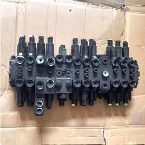
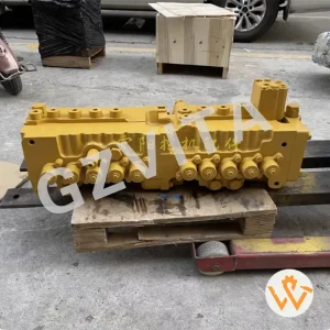
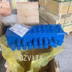
The distribution valve assembly for JCB equipment is an essential component in the hydraulic system, responsible for directing hydraulic fluid to various functions of the machine, such as the boom, bucket, and other attachments. Here are the key components typically found in a JCB distribution valve assembly:

Key Assembly Components

Valve Body

The main housing that contains the internal components and passages for hydraulic fluid.

Spool Valves

These are movable components within the valve body that control the flow of hydraulic fluid to different circuits. They can be shifted to direct fluid to specific functions.

Actuators

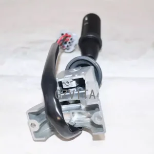
These components are used to operate the spool valves, often controlled by levers or joysticks in the operator's cab.

Seals and O-rings

These are used to prevent hydraulic fluid leaks and maintain pressure within the system.

System Connectors & Control Features

Ports and Connectors

These are the entry and exit points for hydraulic fluid, connecting the distribution valve to the hydraulic lines leading to various machine functions.

Pressure Relief Valve

This component helps protect the hydraulic system from excessive pressure by diverting fluid back to the reservoir when necessary.

Return Line

A pathway for hydraulic fluid to return to the reservoir after it has completed its work.

Mounting Bracket

This secures the distribution valve assembly to the machine frame.

Frequently Asked Questions

Q1: What is the main purpose of a JCB distribution valve assembly?

A1: It is a critical component in the hydraulic system responsible for directing hydraulic fluid to different working parts of the machine, such as the boom, bucket, and attachments.

Q2: How do spool valves function within the distribution assembly?

A2: Spool valves are movable internal components that shift to control and direct the flow of hydraulic fluid to various system circuits.

Q3: What role does the pressure relief valve play?

A3: The pressure relief valve protects the hydraulic system from over-pressurization by routing excess fluid back to the reservoir.

Q4: Why are high-quality seals and O-rings necessary?

A4: High-quality seals and O-rings prevent fluid leaks and help maintain consistent operating pressure throughout the hydraulic system.

Q5: How are spool valves controlled by the operator?

A5: Operators control the spool valves via actuators, which are linked to levers or joysticks inside the operator's cab.

Q6: What is the function of the mounting bracket?

A6: The mounting bracket physically secures the distribution valve assembly to the main frame of the JCB equipment to ensure stability during operation.

Related Products