Wholesale SY16C SY18C SY26 Final Drive Travel Motor Assy For Sany travel reduction gearbox 1725.330.097 Sunward Intelligent18 Supplier, Suppliers

Daily visual inspection – Check for external leaks, damage, or loose connections.

Monitor hydraulic oil level and cleanliness – Ensure proper oil quality and quantity.

Check final drive oil level – Verify oil level in the reduction gearbox.

Listen for unusual noises – Grinding, knocking, or whining sounds indicate issues.

Inspect mounting bolts – Ensure all fasteners are tight and secure.

Monitor travel performance – Note any slipping, uneven movement, or loss of power.

Check for overheating – Touch the motor housing (safely) after operation.

Inspect breathers and vents – Ensure they are clean and unclogged.

Examine travel chains and sprockets – Look for excessive wear or misalignment.

Verify track tension – Proper tension reduces stress on the motor.

Avoid sharp turns on hard surfaces – Minimize stress on the travel system.

Prevent contamination – Keep the area around seals and connections clean.

Operate smoothly – Avoid sudden starts, stops, or direction changes.

Check case drain flow – Ensure minimal leakage from the drain port.

Monitor system pressure – Abnormal pressure may indicate motor or pump issues.

Inspect electrical connections – For electrically controlled motors, check wiring.

Lubricate external linkages – Grease pivot points as per manual.

Avoid continuous high-speed travel – Especially on inclines or rough terrain.

Check parking brake function – Ensure it holds securely on slopes.

Inspect anti-rotation devices – Ensure they are intact and functional.

Record operating hours – Schedule maintenance based on service intervals.

Use correct hydraulic oil – Follow manufacturer’s viscosity and grade recommendations.

Bleed air from the system – If the motor feels spongy or weak.

Check alignment with final drive – Misalignment causes premature wear.

Monitor for oil contamination – Metal particles in oil indicate internal wear.

Inspect seal surfaces – Look for scratches or damage that could cause leaks.

Avoid overloading – Do not exceed the machine’s travel capacity.

Keep travel paths clear – Remove debris that could jam the tracks or sprockets.

Train operators – Ensure proper use and early problem recognition.

Follow manufacturer’s maintenance schedule – Adhere to recommended service intervals for oil changes, filter replacements, and inspections.

Product Description

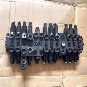
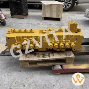
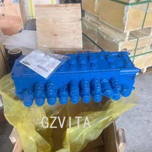
The distribution valve assembly for JCB equipment is an essential component in the hydraulic system, responsible for directing hydraulic fluid to various functions of the machine, such as the boom, bucket, and other attachments. Here are the key components typically found in a JCB distribution valve assembly:

Key Valve Components
Valve Body

The main housing that contains the internal components and passages for hydraulic fluid.

Spool Valves

These are movable components within the valve body that control the flow of hydraulic fluid to different circuits. They can be shifted to direct fluid to specific functions.

Actuators

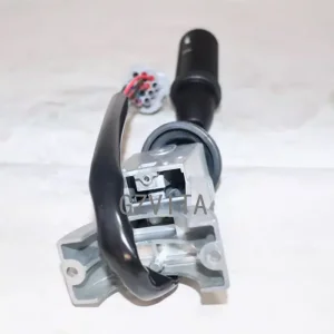
These components are used to operate the spool valves, often controlled by levers or joysticks in the operator's cab.

Seals and O-rings

These are used to prevent hydraulic fluid leaks and maintain pressure within the system.

System Connections and Control
Ports and Connectors

These are the entry and exit points for hydraulic fluid, connecting the distribution valve to the hydraulic lines leading to various machine functions.

Pressure Relief Valve

This component helps protect the hydraulic system from excessive pressure by diverting fluid back to the reservoir when necessary.

Return Line

A pathway for hydraulic fluid to return to the reservoir after it has completed its work.

Mounting Bracket

This secures the distribution valve assembly to the machine frame.

Frequently Asked Questions
What does a distribution valve assembly do in JCB equipment?

It manages and directs the flow of hydraulic fluid to various working elements like the boom, bucket, and other attachments, allowing for precise control of the machinery.

How do the spool valves operate within the assembly?

Spool valves are movable internal components shifted via levers or joysticks in the cab. By shifting positions, they open or block specific fluid channels to activate hydraulic functions.

Why is the pressure relief valve critical?

It serves as a safety mechanism. When hydraulic pressure exceeds a pre-set limit, the relief valve opens to route fluid back to the reservoir, preventing system failures or blown lines.

What happens if the seals and O-rings fail?

Damaged seals will lead to hydraulic fluid leakage, drop in operating pressure, and a loss of performance or control in the attachments. Regular inspection and replacement are highly recommended.

What role does the return line play in this system?

Once the hydraulic fluid has passed through the actuators and completed its power delivery, the return line carries it back safely to the main reservoir to repeat the cycle.

Related Products